How to make Extensive Green roofs?
Introduction
An extensive green roof is a completely natural form of roof covering that uses a low-maintenance planting scheme consisting of hardy, drought-resistant plants. The plants used should be selfregenerating, predominantly short-growing, densely planted, and exhibit a high degree of adaptability to survive in relatively extreme climatic conditions (drought, sun, wind, frost, etc.). Ideally, the plants should originate from the Central European flora, although when choosing the plants, regional variations and local climatic conditions are to be considered.
Compared to intensive green roofs*, the range of potential uses along with the diversity of design and planting schemes are quite restricted. The plants selected should require minimal moisture and demand little from the substrate in the way of nutrients.
In general, irrigation systems are unnecessary for extensive installations, although irrigation may be required during the early stages to support germination and initial growth. An extensive green roof is chosen primarily for aesthetic and ecological reasons and as such, is not designed to be walked upon, except for occasional maintenance and control purposes. Since the types of plants used make comparatively modest demands on the layer configuration, the overall weight, the composition depth, and the loading of the extensive green roof is relatively small.
Features of an extensive green roof:
- limited plant selection and design possibilities
- low maintenance – normally no more than two inspections per year
- shallow composition depth – 77 mm and up
- minimal dead load – starting from approx. 35 kg/m2 including plants
- economical installation and maintenance
- total freedom of design
* Intensive green roofs can be considered as comparable to more traditional soft landscaping schemes in terms of potential use and diversity of design.
Planting can include lawn, shrubs, bushes and even the occasional tree.
1 Design considerations
1.1 Standards
CE-marking hEN 13252
Geotextiles and geotextile-related products for use in drainage systems must bear a CE marking pursuant to the European Standard hEN 13252 ‘Geotextiles and geotextile-related products – Characteristics required for use in drainage systems’. Drainage systems are defined as systems that collect and transport precipitation, ground water and/or other liquids or gases via a geotextile or a geotextile-related product.
This European Standard covers more than just geotextiles such as filter membranes and filter fabrics. Geotextile-related products such as geocomposites (drainage channels and drainage panels) and geospacers (nubbed film and nubbed panels [so-called eggbox-shaped dimples]) are also covered by this standard (hEN ISO 10318 ‘Geosynthetics – Part 1: Terms and definitions’).
The manufacturer is responsible for issuing a Declaration of Performance (DoP) relating to the essential characteristics of the geotextiles and drainage channels that it has brought onto the market pursuant to the European Standard hEN 13252). Part of the Declaration of Performance is an internal production control system that is assessed annually by a certification institute (Notified Body). The product therefore satisfies the national provisions set by the European Member States with regard to the essential characteristics of construction products. All geotextiles and geotextile-related products brought onto the market by manufacturers have to bear the CE-marking.
FLL-Guideline for the Planning, Construction and Maintenance of Green Roofing, published 2008
There are no European standards which specify the design of green roofs. The FLL-(a research institute in Germany) has drawn up a guide for the design, installation and maintenance of green roofs.
This guide sets out the basic principles and requirements that, in general, apply to the design, installation and maintenance of green roofs. This guide is based upon scientific research and practical experience in building green roofs in Germany over the past 20 years.
In many countries throughout Europe this document has been accepted as the key guide for building green roofs. This guide is also based upon this FLL-Green Roof Guideline (2008).
1.2 Design loads
The structural deck should be able to withstand and absorb the static and dynamic loads imposed during construction and final use.
The load on a roof is determined by the:
- permanent imposed load by the weight of the construction
- permanent imposed load by the composition of the green roof
- variable load due to e.g. maintenance work
The assumed permanent load of an extensive green roof at maximum water capacity is shown in table 1. Design loads.
When the substrate is substituted by substrate panels with a thickness of 25 or 50 mm, made by water-absorbing and hydrophilic mineral wool, in combination with vegetation blankets, the design load can be reduced to approx. 35 kg/m2 (respectively 50 kg/m2) with a system depth of approx. 50 mm (or approx. 75 mm).
The assumed permanent load of an extensive green roof at maximum water capacity:

* Weight approx 1.5 tonne/m3 at maximum water capacity
** Optional for usage in a non-root resistant waterproofing membrane
1.3 Roof constructions
The structural deck needs to be able to carry the extra load of the extensive green roof composition. The waterproofing membrane should be root resistant and as with the thermal insulation, be able to carry the permanent load of the extensive green roof composition.
The following roof constructions are recognized:
Cold roof construction
This is a roof construction with an independent ceiling enclosing an air space between the structural deck and the ceiling. When insulation is used it should be placed below the structural deck with a ventilated airspace in between. The load bearing capacity of the structural deck is generally minimal and must correspond to the calculated weight of the extensive green roof. The cooling effect of an extensive green roof can affect the physical properties of the structure. Freezing temperatures on the underside of the structural deck may result in frost damage to the vegetation.

Warm roof construction
This is a roof construction without a ventilated airspace beneath the structural deck. When insulation is used it should be placed on top of the structural deck. It is recommended that a vapour control layer be placed on top of the structural deck underneath the thermal insulation. In general, all types of green roof systems and all forms of vegetation are suitable for use with this type of roof construction.

Inverted roof construction
Insulation is placed on top of the waterproofing membrane. Should an inverted roof be selected for greening, moisture diffusion measures should be considered. When an extensive green roof is installed, a damp-permeable drainage layer must be placed over the thermal insulation in order to protect the insulation from accumulating moisture (internal condensation) over time.
In general, all types of green roof systems and all forms of vegetation are suitable for use with this type of roof provided there is sufficient dead load to prevent uplift of the thermal insulation due to water and wind.

Roof construction without thermal insulation
On top of the structural deck the waterproofing membrane is installed without any thermal insulation. A characteristic of this roof construction is that the space beneath the roof is not heated. Basically all types of green roof systems and all forms ofvegetation are suitable. Freezing temperatures on the underside of the structural deck may result in frost damage to the vegetation.

1.4 Thermal insulation
Thermal insulation needs to be CE-marked based upon the hEN 13162 – 13171 ”Thermal insulation products for buildings. Factory made … Specification”.
There are two different methods for installing thermal insulation to a roof deck:
- IRC = insulation placed above the waterproofing membrane – inverted roof construction
- WRC = insulation is placed beneath the waterproofing membrane – warm roof construction
A cold roof has been omitted as this type of roof construction is rarely used nowadays.

The waterproofing membrane and the applied thermal insulation should be able to withstand short and long term loadings. Should any deformations of the thermal insulation be expected, it should be taken into account when detailing the waterproofing membrane (roof outlet, roof edge, roof protrusion, etc.).
For load class 1, the roofs built on an insulated roof, the thermal insulation should meet minimum load class “dh”.
For load classes 2 and 3 the thermal insulation should meet load class “ds” respectively load class “dx”. The suitability of thermal insulation is to be demonstrated by the manufacturer.
Recommendation
If a paving needs to be installed on top of an insulated roof, it is recommended that an inverted roof construction with XPS insulation or a warm roof construction with cellular glass be chosen. With an inverted roof the waterproofing membrane should be fully bonded with the structural deck, in order that any leak in the waterproofing membrane can be located easily. The XPS insulation panels offer extra protection of the waterproofing membrane during installation of the paving composition.
It is important that a damp-permeable drainage layer is placed on top of the XPS insulation. This allows the panels to dry. Water absorption due to internal condensation will be minimised. It is not necessary to install a separate vapour control layer as the waterproofing itself acts as one. The drainage layer should not damage the top of the insulation panels. Full bonding of the waterproofing membrane is also possible with a warm roof construction if cellular glass is used as thermal insulation. The cellular glass panels are fully bonded with the structural deck and all joints are filled with bitumen. The waterproofing system is thereby fully bonded with the cellular glass panels.
Suitability of the various types of thermal insulation:

* Compressive strength at 10 % deformation in accordance with hEN 826 “Thermal insulating products for building applications. Determination of compression behaviour”
1.5 Waterproofing systems
Continuous waterproofing systems
Roof constructions are, in general, protected against the penetration of water by a waterproofing system (bitumen, synthetic or liquid-applied).
When designing and choosing a waterproofing system, the intended use, applicable standards, regulations and standards of good practice have to be observed. Roof decks should be constructed with adequate falls.
The waterproofing system should be designed to suit the anticipated use. To maintain the integrity of the waterproofing membrane, and to ensure proper construction of the paving, it is essential that the membrane system is being laid as flat as possible.
On trafficked roof decks, horizontal loads caused by vehicle overrun can excessively compress the waterproofing membrane. Such loading should be avoided and therefore separation and slip layers should be built in to the structure.
The waterproofing membrane beneath any vegetation (intensive or extensive planting schemes) should be root resistant or protected against root penetration by a separate root barrier. Root resistance can be proven if the material has passed the FLL-root resistance test or is covered by the British Board of Agrément (BBA) Certification for green roof applications.
The membranes can be applied in one or two layers and attached to the structural deck according to the following methods:
- loose laid and ballasted
- mechanically fixed
- fully bonded.
The composition of a fully bonded waterproofing system can be as follows:
Bitumen – modified bitumen waterproofing membranes
(APP – SBS)
- at least two layers
- first layer: a polyester based roofing felt fully bonded to the structural deck (pour and roll)
- top layer: a root resistant APP or SBS waterproofing membrane fully bonded (torched).
Synthetic waterproofing membranes
- at least two layers
- first layer: a polyester based roofing felt fully bonded to the structural deck (pour and roll method)
- top layer: EPDM, ECB, POCB or TPO waterproofing membrane fully bonded to the first layer.
Liquid-applied roof waterproofing
- Liquid-applied roof waterproofing is regarded as a single layer system.
- It should adhere to the entire surface and be applied in at least two discrete layers.
- A suitable geotextile should be placed in between the layers as a reinforcement.
- The manufacturer should have European Technical Approval in accordance with ETAG 005 “Liquid Applied Roof Waterproofing Kits”.
Mastic asphalt
- The concrete sub-structure needs to be primed before installation.
- As a sub-layer – a root resistant APP – SBS torch-on membrane.
- The asphalt layer with a minimum thickness of 25 mm should be installed on top of the sub-base.
Water-resistant concrete
- Requirements for water-resistant concrete are specified in hEN 206-1 “Concrete. Specification, performance, production and conformity ”and hEN 8500 “Concrete – Complementary British Standard to hEN 206–1 Parts 1 and 2”.
- Cracks in any direction should be limited to ≤ 0.2 mm.
Recommendation
It is recommended that a waterproofing membrane is fully bonded with the structural deck. In many installations leakages occur due to incorrect detailing, poor choice of materials or errors/damage incurred during installation. When a loose laid waterproofing system is damaged, the point of leakage is difficult to locate as the water can move freely over the structural deck. Fully bonded waterproofing systems give much more security if they are installed on a closed structural deck. This means that with insulated roof constructions the choice is limited to a warm roof with cellular glass or PUR and an inverted roof with XPS insulation.
If it has been decided to install a warm roof construction in which the waterproofing membrane is not fully bonded with the structural deck, it is recommended that separate compartments within the vapour control layer be created. In case of any damage to the waterproofing membrane, any leak can be located more easily.
1.6 Details
Basically, the same waterproofing detail principles apply to green roofs as to flat roofs. The waterproofing membrane should be brought up above the surface level by at least 150 mm at roof upstand details e.g. parapets, abutments, and roof protrusions.
Roof edge
If the roof edge is too low, a roof edge profile is placed to retain the composition of the green roof. The roof edge profile can also be used if a roof edge is not present.
At roof edge details, a clear strip of clean gravel (min. Ø 16/32 mm) or concrete slabs should be installed for maintenance and inspection purposes. The minimum recommended width is 300 mm. To prevent the substrate being washed into the clear strip, an Edge Retaining rofile should be installed.

If the waterproofing membrane projects over the roof edge into the ground, it is recommended that the waterproofing membrane extends a minimum 500 mm beyond the edge and at least 200 mm over a joint.
Facade
At facades, the waterproofing membrane should be brought up above the highest roof edge by a minimum of 150 mm above service level. This is not always possible at door thresholds, therefore at those door thresholds where a channel drain is installed, the waterproofing membrane can be brought up above the surface of the clear strip by 50 mm.


Along facades, a clear strip of clean gravel (min. Ø 16/32 mm) or concrete slabs should be installed for maintenance and inspection purposes, and to act as a splashguard. The clear strip between the facade and the vegetated area helps to prevent any water run-off adversely affecting the development of the plants.
To prevent the substrate being washed into the clear strip, an Edge Retaining Profile should be installed. The minimum recommended width of this clear strip is 300 mm.
At facades with an opening (e.g. window, door, etc.) at ≤ 800 mm above the surface level, a clear strip with width of ≥ 500 mm is preferred for enhanced fire safety reasons.

Roof protrusion with or without roof upstand
A minimum 300 mm wide clear strip of clean gravel (min. Ø 16/32 mm) or concrete slabs should be installed for maintenance and inspection purposes. However, a width of 500 mm or more is preferred for enhanced fire safety reasons.
To prevent the substrate being washed into the clear strip, an Edge Retaining Profile should be installed.


Roof outlet
Where a roof outlet is positioned within a vegetated area, an inspection chamber complete with access cover is placed over the outlet to protect it from plant growth and impurities. The inspection chamber should not affect or impede drainage efficiency and must be accessible at all times.

A clear strip of clean gravel (min. Ø 16/32 mm) should be placed around the inspection chamber. The width of this strip should not be less than 500 mm. To prevent substrate being washed into the gravel strip, an Edge Retaining Profile should be installed.
Roof outlets lying outside the vegetation area are normally positioned within a gravelled area, with a gravel guard covering the outlet. When a roof outlet is located within a hard-landscaped area, an inspection chamber fitted with a suitable grating should be placed over this outlet.
1.7 Design of falls – roof slope
For an extensive green roof, falls should ensure that no water is allowed to pond on the roof construction. The construction should be as such that any accumulated water or ponding is prevented from getting into direct contact with the substrate layer at any time.
In order to achieve this, flat roofs should be constructed to a minimum fall of 1 in 80 (~1.3 %). This means that the design fall should be larger, to take into account deflections and inaccuracies in construction. Some designers take a fall of 1 in 80 (~1.3 %) and add an arbitrary adjustment for construction inaccuracies of 25 mm for concrete roofs and 15 mm for metal decks. Roofs with falls of less than 1 in 50 (2 %) are not suitable for single-layer green roof systems. In such cases a separate drainage layer should be installed to ensure that no excess water accumulates in the substrate.
It should be noted that water might pond on the roof covering even though the roof was designed with sufficient falls. This may be due to overlaps of the waterproofing membrane or unexpected inaccuracies in construction or deflection of the roof construction.
Consequently, where the substrate has direct contact with standing water, the substrate will become saturated due to capillary action. A healthy growing environment for the vegetation cannot be guaranteed in such circumstances. By using Drainage Systems with a construction height of 27 mm, direct contact between standing water and the substrate can be avoided.
Roofs with a fall ratio of 1 in 20 or more (≥ 5 %) should have an increased water retention capacity as such relatively steep pitches can result in accelerated and / or excessive water removal from the substrate. This is achieved by increasing the depth of the substrate layer.

Erosion control measures
With increased roof pitch, appropriate soil anchorage measures should be taken against slippage of the loose laid green roof composition layers. An extensive green roof should not be applied if the roof pitch is more than 45°, due to technical difficulties with the vegetation.
Depending on the degree of pitch structural measures and / or vegetation technical measures should be taken.
The slip loading forces should not be transferred to the waterproofing membrane. If necessary, separation and slip layers should beinstalled. The anchorage measures should have drainage openings when installed at the bottom of the roof. When dimensioning the roof outlets, accelerated and / or excessive water discharge has to be taken into account due the increased roof pitch.
Roof slope – falls < 1 in 80
Structural measures:
- roof without a roof edge: a roof edge profile should be installed to restrain the substrate layer and the clear strip
- the width-height ratio of the roof edge profile should be 1:1 with the construction height of the extensive green roof
- the green roof composition layers are placed loose on the waterproofing membrane
- when the green roof composition is not chemically compatible with the waterproofing membrane a separation layer should be installed
- there are no special vegetation technical measures
necessary.
Roof slope – falls 1 in 80 (~0.7 °) to 15 °
Structural and vegetation technical measures:
- roof without a roof edge: a roof edge profile should be installed to restrain the substrate layer and the clear strip
- if stormwater is discharged through a roof gutter, soil anchorage measures at the bottom of the roof should have drainage slots
- the substrate layer should have a higher water retention capacity (higher organic material content or a thicker layer) as the roof pitch can result in accelerated and / or excessive water removal from the substrate
- soil erosion mat or soil erosion glue for improved stability of the substrate.
Roof pitch 15° to 25° (medium pitched roof)
Based upon the increased slippage forces of the green roof composition layers, structural and vegetation technical measures are necessary to improve the stability of the substrate layer.
Structural measures:
- soil anchorage measures at the roof gutter
- installing ND Drainage System
- reinforcing the drainage layer when a single-layer green roof system is installed
- using concrete pavers instead of aggregate at the clear strips
- It is recommended to install a root resistant waterproofing membrane to avoid slippage of the green roof composition
Vegetation technical measures:
- using substrate panels instead of granular material as substrate layer
- reinforcing the substrate layer with geotextiles and
geocomposites - reinforcing the top of the substrate with soil erosion glue
- increasing the number of plug plants
- using vegetation blankets.
Roof pitch 25° to 45° (steep pitched roof)
For roofs with a pitch of 25 ° or more, soil anchorage measures should be taken at the top of the substrate layer. When dimensioning the aggregate strip, the drainage system and the channel drain at
the bottom of the pitched roof, accelerated and/or excessive water removal from the roof has to be taken into account.
Basically, the same structural and vegetation technical measure apply to roofs with a pitch of 25 ° to 45 ° as for roofs with a pitch of 15 ° to 25 °. In addition the following measures should be taken:
Structural measures:
- assessment of the permanent load at the bottom of the roof
- limiting the permanent load at the bottom of the roof by installing soil anchorage measures
- distributing the slip loading forces of the substrate layer over both sides of the roof (saddle roof)
- limiting of the slip loading by fixing geotextiles, drainage composites, geogrids at the top of the roof
- use of grass pavers to prevent aggregate and substrate slippage at the edges of the green roof
- special ladder systems need to be installed for
maintenance - installing Erosion Protection Profile in combination with Erosion Protection Grid.
Vegetation technical measures:
- use of substrate panels instead of granular material as substrate layer
- use of reinforced sedum blankets.
1.8 Designing for stormwater
Roof drainage
hEN 12056-3 ”Gravity Drainage Systems inside buildings. Roof drainage, layout and calculation” provides for a run-off coefficient to allow for absorbent roofing surfaces where national and local regulations, and practice, permit.
For roofs with a fall of 1 in 40 (2.5 %) or flatter (nominally flat roofs) the designer should use a hEN 12056-3 Category 1 storm event for design purposes. This storm event will occur on average once per year and will generate rainfall intensities which vary from 0.01 l/(s.m2) to 0.022 l/(s.m2) depending on geographical location. This is very short duration thunderstorm rain, and will occur on average for 2 minutes, usually in summer, when a green roof composition could be expected to be at its driest.
In using this method, it is assumed that any storm greater than this intensity would be absorbed into the green roof composition, or would pond on any hard surfacing between green areas. The roof deck should however be strong enough to resist the loads imposed by minor ponding, as it should have been designed to cope with the loadings from the green roof.
For roof falls greater than 1 in 40 (2.5 %), a hEN 12056-3 Category 2 or 3 storm event should be used, as there is a risk of structurally significant ponding in the event of the green roof area not be capable of absorbing all the stormwater. Category 2 and 3 storm events are based on the building life multiplied by a factor of safety of 1.5 or 4.5, and results in much higher rainfall intensities (0.029 l/(s.m2) to 0.088 l/(s.m2)).
Run-off coefficients
For extensive green roofs, the following water run-off coefficients (C) can be used. The values depend on the depth of the growing medium and the roof slope:

These figures apply for the stated layer depth at a 15 minute rainfall intensity of r = 0.03 l/(s.m2). The substrate has previously been saturated with water and drip-dried for 24 hours prior to testing.
Annual stormwater retention capacity
The annual average percentage of stormwater actually retained by a green roof is calculated as the difference between the amount of rainfall and the amount of water discharged. The inverse of this is the annual run-off coefficient, Ca. The annual stormwater retention depends more on the depth of the growing medium layer than on the type of composition and composition of the layers.
The annual average percentage of stormwater retention and the run-off coefficient of a green roof system at various construction heights, assuming an annual precipitation rate of 650 – 800 mm:

At a higher (> 800 mm) or lower (< 650 mm) annual precipitation rate the annual average stormwater retention will be lower or higher as stated in table 6.
1.9 Fall protection
On flat roofs, all necessary safety measures for carrying out inspection and maintenance work should be considered at the design stage. Planning for adequate safety precautions at the design stage eliminates potentially higher costs that may be incurred should fall protection safety measures need to be installed at a later date.
Collective preventive measures, e.g. guard-rails, toeboards, barriers, etc., should be installed. Personal fall protection equipment to prevent or minimise the consequences of a fall should only be considered when collective preventive measures are not practical.
Personal fall protection equipment that prevents a fall, e.g. a work restraint system, should always take priority over personal equipment which only limits the height and/or consequences of a fall, e.g. a fall arrest system.
The products and systems must meet the relevant safety standard including hEN 795 “Protection against falls from a height. Anchor devices. Requirements and testing” and hEN 353-1 “Personal protective equipment against falls from a height. Guided type fall arresters including a rigid anchor line”.
The following safety systems should be installed depending on suitability:
- collective preventive systems – guard rails, toe boards, barriers, etc.
- work restraint systems enable the user access to conduct his duties but prevent him from reaching a point where a fall could occur
- work positioning systems equipment enable the user to work intension or suspension to prevent or limit a fall
- fall arrest systems and equipment limit the impact force of a fall on the user and prevent them hitting the ground
1.10 Fire prevention
Enhancing fire safety
Green roofs with an extensive planting scheme are regarded as fire-resistant to radiant heat or flying sparks if:
- the depth of the substrate layer is not less than 30 mm and contains a maximum of 20 % organic material by weight
- a strip of clean gravel (min. 16/32 mm) or concrete slabs with a minimum width of 500 mm is installed around roof protrusions (e.g. skylights, vent pipes, outlets, etc.)
- along facades with an opening (e.g. window, door, etc.) at ≤800 mm above the surface level, a clear strip of clean gravel min. 16/32 mm) or concrete slabs with a minimum width of 500 mm is installed
- at separations not exceeding 40 m, there is a fire-wall with a height of not less than 300 mm, or there is a strip of clean min. 16/32 mm gravel or concrete slabs measuring not less than 1,000 mm in width
- for adjoining, gabled buildings, the first 1,000 mm from the eaves is kept free of vegetation and the area is covered with a non-combustible roof covering.


Width of clear strips (vegetation-free zones):

1.11 Wind loads
Waterproofing membranes and green roof layers have to be designed to take into account wind loads. It is the engineer’s responsibility to determine the appropriate dead loads and the position thereof.
It should be noted that the potential for wind uplift is greatest at the roof perimeters and so protective measures, such as gravel strips or concrete slabs, may be required. Where waterproofing membranes are laid loose without being permanently fixed to the deck structure, the green roof layers may act as a ballast. The determining factor will be the dry weight of these layers.
In addition, the following is to be taken into consideration:
- the variable height, thickness and density of the vegetation
- the weight of the vegetation
- the open, airy nature of the planting that reduces the wind uplift of the vegetation layer.
These criteria are to be included in the design wind loads calculations.
1.12 Protection from emissions
The plants may be subjected to dehydration and frost damage due to exposure to excessive warmth, cold air and / or air currents caused by ventilation systems and air conditioning. Further, gases from chimneys and exhaust systems can cause direct damage to the vegetation. A clear strip, the area / width depending on the effect of the emission, is to be observed.
1.13 Maintenance
It is recommended that a maintenance contract and a longterm care plan is drawn up between the property owner and the landscape contractor.
The care plan should, naturally, cover essential maintenance of the plants, but it is essential that the following points are also considered:
- functionality of the drainage system
- inspection for impurities, deposits and root growth in the inspection chambers
- inspection of the waterproofing system on damages
2 The composition of an extensive green roof
2.1 Composition
The composition of an extensive green roof comprises the following layers that are considered in subsequent sections:
- root barrier layer
- separation and protection layer
- drainage layer
- filter layer
- substrate layer
- vegetation layer.
The various layers need to be geared in such a way that the functionality of the total composition is guaranteed. Each layer has a specific function in the green roof system composition. It is possible that one product integrates the functions of several layers or that one layer consists of more than one product e.g. the drainage systems integrate the drainage and filter layer and, in certain compositions, also include the separation and protection layer.
Multi-layer green roof composition – Standard
In a multi-layer green roof composition the substrate layer is separated from the drainage layer by means of a filter fabric. The filter fabric prevents finer particles from the substrate entering the drainage layer. This filtration ensures that a fully functional horizontal and vertical drainage is maintained at all times.
As the substrate layer does not function as a drainage component it can be mixed with organic-based material to improve moisture retention and nutrient supply, thereby increasing the buffering action and simultaneously improving plant growth.
Advantages of a multi-layer system:
- enhanced moisture-retention of the substrate promotes healthy plants over the longer term
- excellent long-term horizontal and vertical drainage preventing additional dead loads on the roof structure caused by rainwater ponding
- good buffering action in the substrate provided by the presence of both finer particles and organic material suitable for both flat and pitched roofs.
Single-layer green roof composition – Non-standard
In a single-layer green roof composition, a mineral substrate undertakes the functions of the substrate, the filtration, and the drainage. The substrate should be filter-stable, that is it should be inert, non-degradable and remain of a size that will not compromise the filtration function of the layer, while allowing good vertical and horizontal drainage. The minimum roof fall of a single-layer system should be 1 in 50 (2 %) and the substrate should have a minimum depth of 80 mm. Since there is no separate filter layer in this system, the substrate may contain only very little organic material. It should be noted that, as the substrate is a natural material, it is difficult to quantify drainage performance, and care should be exercised as the inevitable growth in root density and the ingress of finer particles will probably reduce performance over time.
Disadvantages of a single-layer system:
- poor long-term horizontal drainage, and the permitted design loads may be exceeded due to water accumulation
- poor / inefficient drainage increases the accumulation of moisture in the substrate. Excessive humidity leads to the growth of mosses and attracts maintenance-intensive plants
- reduced buffering action from water and nutrients as the substrate does not contain any organic material
- significant fluctuations in water and nutrient balance leads to stress within the vegetation layer, which in turn, can result in poor growth or even death of the plants
- not suitable for roofs with falls of less than 1 in 50 (2 %)
- the anticipated cost savings made by omitting a separate filter and drainage layer are cancelled out by the need for increased levels of maintenance.
Where the roof fall is less than 1 in 50 (2 %), the horizontal drainage should be improved by installing a strip drainage system.
The strips are laid flat, in parallel rows at approximately 2 meters intervals on top of the protection layer. The strips are linked into an inspection chamber that is placed on top of a roof outlet.
2.2 Root barrier layer
The root barrier layer prevents the ingress of roots into the waterproofing layer. The root barrier layer can be integrated in a root resistant waterproofing membrane (e.g. PVC, EPDM or bitumen-copper waterproofing membranes tested in accordance with the DIN 4062-1 test) or hEN 13948 “Flexible sheets for waterproofing. Bitumen, plastic and rubber sheets for roof waterproofing. Determination of resistance to root penetration”.
If the waterproofing membrane is not root resistant, a separate root barrier should be placed directly on top of the waterproofing membrane. Overlaps have to be heat-welded along the lapped joints. Use of a separate root barrier on top of the waterproofing membrane is not required in those situations where the waterproofing membrane is root resistant.
Note
For the installation of a separate root barrier the same detail principles apply as for the installation of a waterproofing membrane. On inverted roof constructions lacking a root-resistant waterproofing membrane, the root barrier is positioned directly beneath the thermal insulation and on top of the waterproofing membrane.
The root barrier is a 0.5 mm modified LDPE sheet tested in accordance DIN 4062-1.
2.3 Separation, protection and slip layer
The separation layer separates materials that are chemically incompatible (e.g. Polyvinyl Chloride (PVC) and Polystyrene (PS)).
The separation layer also acts as a protection layer. The protection layer guards the waterproofing membrane against mechanical and dynamic loadings. When using a separate protection layer, this should be a protective membrane, a rubber mat, or a geotextile with a minimum weight of 300 g/m2 and a thickness of > 2 mm (puncture resistance of 1.1 kN). The protection layer should be designed to suit the conditions to which the waterproofing membrane will be subjected.
If Drainage Systems are fitted immediately after installation of the waterproofing membrane, they can act as a separation and protection layer for lightweight static loads such as an extensive green roof.
2.4 Drainage layer
The drainage layer relieves the waterproofing membrane of hydrostatic pressure. In addition, any excess water in the substrate layer is led away, preventing potential ponding of water in the substrate that may damage the vegetation.
The drainage layer must have a good vertical permeability combined with the ability to transport excess water horizontally away from the roof area. It must maintain full functionality for a period of 50 years, in compliance with DIN 4095 ”Drainage and protection of sub-structures – design, dimensioning and installation”.
The drainage capacity should be specified in l/(s.m) taking into account the roof slope/pitch and the expected load pressure. Any drainage system, including eggbox-shaped dimpled plastic sheets (geospacers), that forms part of a drainage system, must be CE-marked according to hEN 13252.
2.5 Filter layer
It is essential that the drainage layer should be permanently protected against clogging by fine particles present in the substrate. This is achieved by using a woven or a non-woven filter fabric to retain these fine particles. The weight of this geotextile is approx. 100-200 g/m2, depending on load, and the pore size should correspond to the minimum particle size of the substrate.
In general, the geotextile should have a puncture strength of 0.5 kN and a pore opening size of < 200 mμ (0.2 mm). The filter layer should allow roots to grow through into the drainage layer.
Note
The woven / non-woven filter fabrics must overlap by least 100 mm. In situations where the filter layer (geotextile) as part of a drainage system is placed on top of an eggbox-shaped dimpled plastic sheet (geospacer) or a granular material, the geotextile as well as the geospacer must be CE-marked (hEN 13252).
2.6 Drainage Systems
Drainage Systems comprise the filter layer, the drainage layer, and the separation and protection layer as one integrated unit. The construction height of the Drainage System is between 8 and 27 mm. A filter fabric (woven or non-woven) is bonded to each dimple. Depending on the application, the core may be perforated and provided with a plastic film or a geotextile on the back.The dimples of the Drainage System act as an additional water reservoir for the vegetation.
The Drainage Systems with a perforated core prevent the formation of a vapour control layer on top of the XPS thermal insulation. The top of the XPS insulation panels can dry out and therefore internal condensation is minimised. The insulation value (R-value) over time is not affected.
Dimensioning Drainage Systems
The amount of water that needs to be discharged by the drainage layer (q’) can be calculated per l/(s.m) by using the following equation:
q’ = A x C x r / Lr, in l/(s.m)
q’ = required amount of water to be discharged by the drainage layer l/(s.m)
A = effective roof area m2 (Lr x Br)
C = run-off coefficient (see table 6)
r = rainfall intensity l/(s.m2)
Lr = length of the roof to be drained m

Lr = the length of roof to be drained
Br = the plan width of roof from gutter to ridge
Hr = the height of roof from gutter to ridge
Tr = the distance from gutter to ridge measured along the roof
2.7 Substrate layer
The composition of the substrate is important for the health and growth of the plants. The substrate needs to be capable of retaining water, making sufficient quantities of water accessible to the plants whilst allowing any water surplus to be discharged to the drainage layer.
Granular material
The substrate layer for an extensive green roof should contain a low proportion of organic materials (≤ 65 g/l). The FLL-Green Roof Guideline (2008) has defined the exact requirements of such a substrate. The high mineral content is designed to minimise possible shrinkage of the substrate during prolonged dry periods, and consequent damage to roots. An excessively high organic content may result in a significant degree of settlement or “sag” that will require regular “topping-up”.
A single-layer system uses a substrate with a very low proportion of organic material (≤ 40 g/l). On roofs with falls of more than 1 in 19 (roof pitch 5 %), a thicker substrate layer should be installed to achieve a higher water retention capacity. Due to the falls water is discharged more quickly from the substrate layer.
The depth of the substrate is determined by the vegetation’s requirements for water, nutrients and root space:
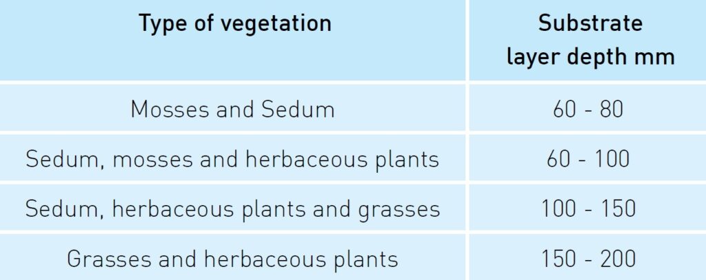
When calculating the required layer depth, the following should be taken into consideration:
- characteristics of the various materials to be used
- roof slope
- exposure of the roof surface (sun, shadow, wind, etc.)
- regional climate
- object-specific conditions
- structural dead load and superimposed load
- target water retention.
Note
Improved topsoils and / or sub-soils are likely to contain a significant proportion of finer particles that can clog the drainage and filter layer. In view of this, it is recommended that soils and soil-based substrates should not be used with extensive green roofs. The ND DGS Substrates comply with the FLL-Green Roof Guideline (2008).
Delivery
The most appropriate form of delivery is determined by the size and location of the project. There may be losses of approx. 15 % due to settlement.
Substrate panels
For extensive green roofs, the substrate can be replaced by Substrate Panels, manufactured using a hydrophilic (water-absorbing) mineral wool. Due to their low weight, substrate panels are ideal for use in constructing lightweight green roofs.
The Substrate Panels in combination with Vegetation Blankets reduce the total weight of an extensive green roof to 40 kg/m2 for the 25 mm Substrate Panels and to 50 kg/m2 for the 50 mm Substrate Panels. The substrate panels offer an economic solution for small roof surfaces (no need for a heavy crane). When the 25 mm Substrate Panels are used extra maintenance is to be expected (fertilising and watering) due to the shallow construction height.
The 100 % mineral content and high density give these substrate panels a high degree of durability along with structural stability. It makes these panels ideal for constructing extensive green roof on pitched roofs. Where granular material may slide off, the mineral wool panels remains in place. At a roof pitch of more than 15° structural measures need to be taken.
By using a plug cutter holes can easily be formed into the substrate panels, and the root balls of the plug plants fit exactly into the prepared holes. It is also possible to scatter sedum cuttings (by hand or by a hydroseeding machine) or to unroll vegetation blankets on top of the substrate panels. When sedum cuttings or plug plants are used, the substrate panels should be mulched with 10 – 20 mm of Substrate Mineral. The high water retention capacity of the mineral wool panels enables the planting of more demanding vegetation like taller herbaceous plants and grasses.
Advantages:
- quick and easy installation
- low weight
- high water retention.
In order to be used as green roof substrates the Substrate Panels have to be approved by the FLL-Green Roof Guideline as an acceptable substrate substitute. The panels have to be structurally stable and have a water-retaining capacity of 30 l/m2 at a thickness of 50 mm.
2.8 Water retention and water buffering layer
Climate change means that more and more heavy rainfall occurs these days. The current storm water system is often not able to instantly deal with all the water that falls in a sudden heavy shower, resulting in streets and cellars flooding or water spewing out from the storm water system. Excess water and the associated problems resulting from rainfall are seen primarily in urban areas. By making use of water buffering on flat roofs and/or water retention in green roof systems (to slow down the progress of the water), problems caused by excess rainwater can be reduced in these vulnerable, densely built-up areas.
There is the Water Retention Roof System and the Water Buffering Roof System.
The difference between buffering and retention
In the case of water buffering, the rainwater is retained in the green roof system for a lengthy period and then allowed through to the vegetation. In the case of water retention, the rainwater is fed into the storm water system but with a delay.
2.9 Vegetation layer
Plants used on extensive green roofs should be self-regenerating and be able to adapt to both the local environment and the extreme climatic conditions on a roof. They should originate from the Central European flora although regional bio-diversity and prevailing climatic conditions should be taken in to account.
Planting communities used on an extensive green roof:
- mosses and sedum
- sedum, mosses and herbs
- sedum, herbs and grasses
- grasses and herbs.
The vegetation is supplied in the following formats:
- sedum cuttings
- plug plants
- vegetation blankets
The following circumstances are of concern when determining the extensive planting scheme and in determining the success and the durability of an extensive green roof:
Climatic circumstances:
- local climate
- hours of sun
- periods of drought
- annual precipitation
- principal wind direction.
Structural circumstances:
- exposure to sun shade
- position of the roof
- slope / pitch of the roof
- wind flow.
Vegetation technical circumstances:
- resistance against wind flow
- demand on the substrate layer
- suppression resistance
Sedum cuttings
Cuttings can be taken from existing sedum plants without causing any long-term harm to the donor plant. Sedum cuttings should be around 20 mm in length, and after scattering they will root quite easily into the Substrate Extensive, quickly developing into new plants.
Planting on a multi-layer system:
After scattering the sedum cuttings on top of the substrate, ensure good contact by carefully rolling them in.
Planting on a single-layer system:
Since the substrate (substrate) is mainly mineral based, the sedum cuttings will need to be mulched with compost (approx. 10 l/m2). Do not cover the entire area.
Planting on top of a lightweight green roof composition:
After scattering the sedum cuttings on top of the Mineral Wool Substrate Panels, the sedum cuttings must be mulched with approx. 10 mm of Substrate Mineral. This can easily be done by a hydroseeder.
Recommended amount:
Sedum cuttings: 75 – 100 g/m2 a minimum of 100 sedum cuttings/m2 of at least 4 different types
Plug plants
Sedum, herbaceous plants and grasses are specially cultivated as plug plants in flat-bottomed trays for extensive green roofs. The plug plants should be grown in containers of not less than 50 cm3.
Planting in a multi-layer system:
Plant the plug plants into a substrate layer having a depth of at least 60 mm.
Planting in a single-layer system:
The mineral-based substrate also acts as the drainage component and so there should be a minimum of 20 mm beneath the root-ball of the plug plant to prevent roots being in direct contact with the drainage layer.
Recommended amount: plug plants: at least 15 plants/m2
Planting in a lightweight green roof composition
It’s important to ensure the holes created penetrate to the full thickness of the substrate panels. Following planting, the Mineral Wool Substrate Panels should be mulched with 10 – 20 mm of Substrate Mineral.
Vegetation blankets
Vegetation blankets are pre-cultivated mats of sedums, herbaceous plants and grasses. The mats should have at least 75 % of their surface area covered, and up to 20 % of the vegetation may consist of non-intentional vegetation, such as weeds, stray plants, etc.
Planting:
The vegetation blankets should be unrolled over the substrate within 48 hours of delivery. When blankets need to be stored temporarily, they must be stored in a cool, dry and shaded location, as the vegetation may be damaged if the rolled mats are allowed to become too warm. For best coverage, the mats should overlap by at least 25 mm. Once laying is complete, the entire composition should be watered until saturated.
Recommended amount: vegetation blankets: surface area + 2.5 %
To be continued.
Extensive Green Roof Systems:
Roof with sufficient fall 1 in 80 (~0.7°) to 15°
a. Warm roof construction / roof
construction without thermal insulation
b. Inverted roof construction
Roof with insufficient fall < 1 in 80
a. Warm roof construction / roof construction without thermal insulation
b. Inverted roof construction
Roof with additional water reservoir
a. Warm roof construction / roof construction without thermal insulation
b. Inverted roof construction
Light weight roof construction falls 1 in 80 (~0.7°) to 15°
Roof with additional water buffer – lightweight
a. Warm roof construction / roof construction without thermal insulation
b. Inverted roof construction
Roof with water retention
Medium pitched roof falls 15° to 25°
a. Multi-layer system
b. Single-layer system
Steep pitched roof falls 25° to 45°