How to make Trafficable roofs?
Walkable and Parking roofs
Introduction
As urbanisation expands and the number of cars on our streets continues to grow, the lack of parking places is forcing us to reconsider our use of space, to maximise its potential, and to investigate the possibility of vertical development. Modern offices, apartment blocks and shopping centres use a combination of hard and soft landscaping on their flat roofs and underground parking facilities to make the most of their limited open space. Careful planning and good design will improve overall living conditions within our cities by creating large, open green areas and places for recreation and leisure, while sub-surface structures provide the necessary underground parking that will prevent it from intruding into the urban environment.
Careful planning by architects and design engineers can maximise the use of valuable open spaces by covering roofs with extensive and/or intensive planting schemes that are combined with suitable hard-landscaping to provide access for vehicles and/or pedestrians. Any design will need to accommodate specific construction requirements such as the required composition depth for elemental paving, the depth of growing medium required by the planting scheme, the maximum permissible surface loads, the provision of a suitable waterproofing system, and so on.
When paving of any type is used, it will not be constructed over a prepared sub-grade, as would normally be the case, but will be constructed on top of a structural deck, and so the design must address the following considerations:
- the difference in behaviour and reaction that can be expected between natural sub-grades and constructed roof decks
- the waterproofing system must be suitable for both static and the dynamic loadings
- the type of roof construction, whether it is a ‘warm roof‘, an inverted roof, or a roof construction without thermal insulation
- the compressive strength of any thermal insulation
- the type and depth of any granular materials, such as sub-base layers or laying courses
- the type, depth and behaviour of any elemental paving
- the anticipated usage and the predicted intensity of use of the roof deck structure by both people and vehicles, and the loads imposed as a consequence of such use.
1. Design considerations
1.1 Standards
CE-marking hEN 13252
Geotextiles and geotextile-related products for use in drainage systems must bear a CE marking pursuant to the European Standard hEN 13252 ‘Geotextiles and geotextile-related products – Characteristics required for use in drainage systems’. Drainage systems are defined as systems that collect and transport precipitation, ground water and/or other liquids or gases via a geotextile or a geotextile-related product.
This European Standard covers more than just geotextiles such as filter membranes and filter fabrics. Geotextile-related products such as geocomposites (drainage channels and drainage panels) and geospacers (nubbed film and nubbed panels [so-called eggbox-shaped dimples]) are also covered by this standard (hEN ISO 10318 ‘Geosynthetics – Part 1: Terms and definitions’).
The manufacturer is responsible for issuing a Declaration of Performance (DoP) relating to the essential characteristics of the geotextiles and drainage channels that it has brought onto the market pursuant to the European Standard hEN 13252). Part of the Declaration of Performance is an internal production control system that is assessed annually by a certification institute (Notified Body). The Declaration of Performance, which is to be published on the manufacturer’s website, entitles the manufacturer to use the CE-marking on its products. The product therefore satisfies the national provisions set by the European Member States with regard to the essential characteristics of construction products. All geotextiles and geotextile-related products brought onto the market by the manufacturers have to bear the CE-marking.
Eurocode 0: hEN 1990 ‘Basis of structural design’ and Eurocode 1: hEN 1991 ‘Actions on structures’
The loads on roofs are determined by:
- the fixed, permanent load resulting from the construction‘s own weight
- the permanent loads due to the weight of the green roof construction / construction of a hard surface
- the additional loads on the roof, for instance due to maintenance work or car/freight traffic
For balconies, galleries and roof-top terraces for which – on the basis of the situation and accessibility – the assumption must be made that people spend time there other than just for repair work and maintenance, the additional load of the construction can be calculated on the basis of hEN 1991-1-1.
hEN 1991-1-1 does not specify loads resulting from vehicles on buildings or parts of buildings that are situated below a public highway or that form part of it.
hEN 1991-2 ‘Traffic loads on bridges’
There are no specific hEN Standards for roofs that need to be accessible for vehicles. hEN 1991-2 includes axle loads and wheel loads that the technical draughtsman can use in their calculations. Traffic on the top level of car parks (the roofs) generally does not differ much from that on public highways.
However, the number of axle loads and the speeds are considerably lower than the calculations in the above-mentioned hEN Standard. Applying these hEN Standards without further consideration gives rise to overdesign of the construction, with considerable financial consequences.
Clear agreements must be made in advance regarding the use and the maximum permitted load of a roof terrace / top level of a car park in a schedule of requirements. Clarity is also required regarding the status of the area in which the Roof Systems are to be used. The basic principles used for the design, development, and construction must be upheld in no uncertain terms in the use. This could include prohibitive signs, barrier arms, or physical obstacles. These measures must guarantee that the maximum permitted load of the roof terrace / top level of a car park is not exceeded in practice.
Based on this functional schedule of requirements, the technical draughtsman will produce a strength analysis and will be required to clearly substantiate the basic principles for the calculation.
1.2 Load classification
There are no published standards governing the construction of elemental pavements over a roof deck in the UK or RoI. Through research in close cooperation with the Technical University in Munich, Germany, the following load classes can be distinguished based up on the intended use of the roof deck.

1.3 Roof constructions
The structural deck needs to be able to carry the extra load of the extensive green roof composition. The waterproofing membrane should be root resistant and as with the thermal insulation, be able to carry the permanent load of the extensive green roof composition.
The following roof constructions are recognized:
Cold roof construction
This is a roof construction with an independent ceiling enclosing an air space between the structural deck and the ceiling. When insulation is used it should be placed below the structural deck with a ventilated airspace in between. The load bearing capacity of the structural deck is generally minimal and must correspond to the calculated weight of the extensive green roof. The cooling effect of an extensive green roof can affect the physical properties of the structure. Freezing temperatures on the underside of the structural deck may result in frost damage to the vegetation.

Warm roof construction
This is a roof construction without a ventilated airspace beneath the structural deck. When insulation is used it should be placed on top of the structural deck. It is recommended that a vapour control layer be placed on top of the structural deck underneath the thermal insulation. In general, all types of green roof systems and all forms of vegetation are suitable for use with this type of roof construction.

Inverted roof construction
Insulation is placed on top of the waterproofing membrane. Should an inverted roof be selected for greening, moisture diffusion measures should be considered. When an extensive green roof is installed, a damp-permeable drainage layer must be placed over the thermal insulation in order to protect the insulation from accumulating moisture (internal condensation) over time.
In general, all types of green roof systems and all forms of vegetation are suitable for use with this type of roof provided there is sufficient dead load to prevent uplift of the thermal insulation due to water and wind.

Roof construction without thermal insulation
On top of the structural deck the waterproofing membrane is installed without any thermal insulation. A characteristic of this roof construction is that the space beneath the roof is not heated. Basically all types of green roof systems and all forms ofvegetation are suitable. Freezing temperatures on the underside of the structural deck may result in frost damage to the vegetation.

1.4 Thermal insulation
Thermal insulation needs to be CE-marked based upon the hEN 13162 – 13171 ”Thermal insulation products for buildings. Factory made … Specification”.
There are two different methods for installing thermal insulation to a roof deck:
- IRC = insulation placed above the waterproofing membrane – inverted roof construction
- WRC = insulation is placed beneath the waterproofing membrane – warm roof construction
A cold roof has been omitted as this type of roof construction is rarely used nowadays.

The waterproofing membrane and the applied thermal insulation should be able to withstand short and long term loadings. Should any deformations of the thermal insulation be expected, it should be taken into account when detailing the waterproofing membrane (roof outlet, roof edge, roof protrusion, etc.). For load class 1, the roofs built on an insulated roof, the thermal insulation should meet minimum load class “dh”. For load classes 2 and 3 the thermal insulation should meet load class “ds” respectively load class “dx”. The suitability of thermal insulation is to be demonstrated by the
manufacturer.
Recommendation
If a paving needs to be installed on top of an insulated roof, it is recommended that an inverted roof construction with XPS insulation or a warm roof construction with cellular glass be chosen. With an inverted roof the waterproofing membrane should be fully bonded with the structural deck, in order that any leak in the waterproofing membrane can be located easily. The XPS insulation panels offer extra protection of the waterproofing membrane during installation of the paving composition.
It is important that a damp-permeable drainage layer is placed on top of the XPS insulation. This allows the panels to dry. Water absorption due to internal condensation will be minimised. It is not necessary to install a separate vapour control layer as the waterproofing itself acts as one. The drainage layer should not damage the top of the insulation panels. Full bonding of the waterproofing membrane is also possible with a warm roof construction if cellular glass is used as thermal insulation. The cellular glass panels are fully bonded with the structural deck and all joints are filled with bitumen. The waterproofing system is thereby fully bonded with the cellular glass panels.
Suitability of the various types of thermal insulation:

* Compressive strength at 10 % deformation in accordance with hEN 826 “Thermal insulating products for building applications. Determination of compression behaviour”
1.5 Waterproofing systems
Continuous waterproofing systems
Roof constructions are, in general, protected against the penetration of water by a waterproofing system (bitumen, synthetic or liquid-applied).
When designing and choosing a waterproofing system, the intended use, applicable standards, regulations and standards of good practice have to be observed. Roof decks should be constructed with adequate falls.
The waterproofing system should be designed to suit the anticipated use. To maintain the integrity of the waterproofing membrane, and to ensure proper construction of the paving, it is essential that the membrane system is being laid as flat as possible.
On trafficked roof decks, horizontal loads caused by vehicle overrun can excessively compress the waterproofing membrane. Such loading should be avoided and therefore separation and slip layers should be built in to the structure.
The waterproofing membrane beneath any vegetation (intensive or extensive planting schemes) should be root resistant or protected against root penetration by a separate root barrier. Root resistance can be proven if the material has passed the FLL-root resistance test or is covered by the British Board of Agrément (BBA) Certification for green roof applications.
The membranes can be applied in one or two layers and attached to the structural deck according to the following methods:
- loose laid and ballasted
- mechanically fixed
- fully bonded.
The composition of a fully bonded waterproofing system can be as follows:
Bitumen – modified bitumen waterproofing membranes
(APP – SBS)
- at least two layers
- first layer: a polyester based roofing felt fully bonded to the structural deck (pour and roll)
- top layer: a root resistant APP or SBS waterproofing membrane fully bonded (torched).
Synthetic waterproofing membranes
- at least two layers
- first layer: a polyester based roofing felt fully bonded to the structural deck (pour and roll method)
- top layer: EPDM, ECB, POCB or TPO waterproofing membrane fully bonded to the first layer.
Liquid-applied roof waterproofing
- Liquid-applied roof waterproofing is regarded as a single layer system.
- It should adhere to the entire surface and be applied in at least two discrete layers.
- A suitable geotextile should be placed in between the layers as a reinforcement.
- The manufacturer should have European Technical Approval in accordance with ETAG 005 “Liquid Applied Roof Waterproofing Kits”.
Mastic asphalt
- The concrete sub-structure needs to be primed before installation.
- As a sub-layer – a root resistant APP – SBS torch-on membrane.
- The asphalt layer with a minimum thickness of 25 mm should be installed on top of the sub-base.
Water-resistant concrete
- Requirements for water-resistant concrete are specified in
hEN 206-1 “Concrete. Specification, performance, production
and conformity ”and hEN 8500 “Concrete – Complementary British Standard to hEN 206–1 Parts 1 and 2”. - Cracks in any direction should be limited to ≤ 0.2 mm.
Recommendation
It is recommended that a waterproofing membrane is fully bonded with the structural deck. In many installations leakages occur due to incorrect detailing, poor choice of materials or errors/damage incurred during installation. When a loose laid waterproofing system is damaged, the point of leakage is difficult to locate as the water can move freely over the structural deck. Fully bonded waterproofing systems give much more security if they are installed on a closed structural deck. This means that with insulated roof constructions the choice is limited to a warm roof with cellular glass or PUR and an inverted roof with XPS insulation.
If it has been decided to install a warm roof construction in which the waterproofing membrane is not fully bonded with the structural deck, it is recommended that separate compartments within the vapour control layer be created. In case of any damage to the waterproofing membrane, any leak can be located more easily.
1.6 Details
Basically, the same waterproofing detail principles apply to hard landscaped roof decks as to flat roof decks. The waterproofing membrane should be brought up above the surface level (paving) by at least 150 mm.
At door thresholds (detail 1) where a drainage channel is installed, the waterproofing membrane can be brought up above the surface of the paving by 50 mm.

If the waterproofing membrane projects over the roof edge into the ground, it is recommended that the waterproofing membrane extends a minimum 500 mm beyond the edge and at least 200 mm over a joint.
When paving is placed against the façade, a rubber strip is placed between the paving and the waterproofing membrane to protect the waterproofing membrane against mechanical damage (detail 2).


1.7 Design of falls – structural roof deck
The structural deck of a trafficked roof deck should be constructed with adequate falls to prevent water ponding on the waterproofing membrane, the sub-base, and/or the laying course. Falls should be in such a way that surface water is directed off and away from the structural deck as quickly as possible.
In order to achieve satisfactory drainage, trafficked roof decks should have a fall of not less than 1 in 80 (~1.3 %). However, because of the risk of settlement, roof deflection and construction inaccuracies, a fall greater than 1 in 80 should always be stipulated.
It is both practical and economic to design using falls of 1 in 40.
However, on some buildings this can prove to be an excessively severe design criterion. As an alternative, the designer may elect to use a fall of 1 in 80, and then add a further 25 mm of fall for concrete roof decks or an additional 15 mm of fall for metal roof decks.
Recommended falls of a structural deck:
- load class 1 ≥ 1 in 50
- load classes 2 and 3 ≥ 1 in 40
Falls beneath the water proofing membrane can be achieved:
- in the structural deck
- by screed to falls
- by tapered thermal insulation
Note:
If water is ponding on the structural deck due to a lack of sufficient falls additional measures need to be taken in respect of the drainage and possible frost damage of the paving composition.
Possible solutions are:
- the use of a geocomposite suitable for a roof with no fall with a specification of the drainage length
- the use of a “no fines” sub-base material (material with no part cles smaller than 1 mm)
- the use of a “no fines” laying course material when the paving is placed directly on top of the Drainage Systems
- the use of a no-fines permeable concrete.
The most suitable solution depends on the individual project.
1.8 Roof drainage
On roof decks carrying an elemental pavement, drainage of surface water and seepage water is achieved by means of roof outlets. The roof outlets are connected to a gravity drainage system within or outside the building that directs collected water to a conventional sub-surface stormwater system or over the edge of the roof deck. All surface and seepage water should be discharged at standard atmospheric pressure and without any attenuation.
Three discharge levels are identified:
- 1st level – waterproofing membrane
- 2nd level – elemental paving
- 3rd level – thermal insulation (inverted roof)
Stormwater discharge via gravity drainage inside a building – roof outlets
Roof outlets have to be placed at the lowest point of the roof. They have to be dimensioned in accordance with hEN 12056-3 “Gravity Drainage Systems Inside Buildings” and be accessible for inspection at all times. The roof outlets must collect and discharge both the surface water run-off from the paving along with any water that penetrates the paving joints and enters the laying course.
Roof outlets located within a paved area should incorporate an inspection chamber with a gully top grating laid flush with the paving. The class of the inspection chamber and the gully top grating should match or exceed the load class of the overall roof deck. The inspection chamber should also incorporate a silt trap. Point loads on the inspection chamber should be dispersed over the sub-base or drainage layer.
The shaft of the inspection chamber should enable collection and discharge of water from the 1st discharge level (waterproofing membrane) and the 3rd discharge level (thermal insulation inverted roof). The gully top grating should be able to collect the water from the 2nd (elemental paving) discharge level.
The requirements of the gully top grating depend on the load class (hEN 124 “Gully tops and manhole tops for vehicular and pedestrian areas”):
- load class 1 = gully top grating class A
- load class 2 = gully top grating class B
- load class 3 = gully top grating class D

Linear drainage channel
The laying course or support layer for a linear drainage channel must not obstruct or block the horizontal flow of the drainage layer. Linear drainage channels may be used as an alternative to inspection chambers with a gully top grating. The gratings of the linear drainage channel units should permit collection and discharge of the surface water without the need for any additional pressure or attenuation.
Both drainage channel and grating must match or exceed the load class of the roof deck hEN 1433 “Drainage channels for vehicular and pedestrian areas – Classification, design and testing requirements, marking and evaluation of conformity” and hEN 124. The linear drainage channels should be connected through appropriate inspection chambers to roof outlets and when placed in front of façades/door thresholds can discharge through the drainage layer.
Surface water from adjacent roofs and facades
When determining the surface water discharge requirement of a roof deck, it is essential that any potential discharges from adjacent roofs and façades are accommodated. If such accommodation is not possible, adequate provision for independent drainage of these adjacent roofs must be made. Run-off from adjacent facades can be collected and discharged using aggregate strips and/or linear drainage channels connected to appropriate roof outlets or the drainage layer.
Stormwater discharge over the roof edge
Surface water can also be collected by a roof-edge gutter system, or discharged over the roof edge into the adjacent ground. A filter or fin drain construction (trench of clean, free-draining, inert aggregate surrounding a perforated pipe that is wrapped in a geotextile) must be placed along the edge to prevent inundation and damage to the sub-base of the paved area.
Where vertical walls are present, such as in a basement structure, they must be protected with a suitable Drainage Systems that will prevent any composition of hydrostatic pressure against the sub structure.

2 The build-up of a podium and parking roof deck
The composition of elemental paving comprises the layers listed below, each of which is considered in subsequent sections:
- separation layer
- slip layer
- protection layer
- drainage layer
- filter layer
- sub-base layer
- levelling layer
- laying course
- paving.
The compatibility and cooperation of each of the individual layers is critical to determining a reasonable life-span for a flexibly paved surface. Each layer must have the ability to absorb and constrain the potential dynamic and static loadings, have adequate compressive strength, and must not exhibit any unacceptable short-term flexion.
Normally each layer has its individual function in the total system composition.
However, it is possible that:
- A single product integrates the function of several layers – e.g. the slip layer can also fulfil the function of the separation and protection layer.
- Certain layers use more than one product – e.g. the slip layer needs to have two separate non-adhesive surfaces to enable slippage to occur.
2.1 Separation layer
Chemically incompatible building materials need to be isolated by a separation layer (e.g. Polyvinyl Chloride [PVC] and Polystyrene [PS]).
A separation layer can consist of a:
- plastic sheet
- geotextile.
Incompatible building materials need to be separated (covered) completely.
The Drainage Systems can be provided with a factory-installed separation and slip film, or a moisture diffusion open geotextile on the back.
2.2 Slip layer
During construction, and when in use, flexible pavements impose both vertical and horizontal loads. Horizontal loads are generated by temperature changes within the structure and from external dynamic sources such as braking, acceleration, and turning of vehicles. These vertical and horizontal loads must be borne by the underlying layers. However, it should be noted that waterproofing materials / systems are not capable of withstanding the horizontal loads typical of a flexible pavement and therefore care must be exercised when specifying.
Where there is concern regarding the horizontal load-bearing capacity of the waterproofing membrane, a slip layer, comprising two, smooth, non-sticky surfaces that can move with respect to each other, will be required.
In general plastic sheets manufactured from the following materials are used as a slip layer:
- PET (Polyethylene terephthalate)
- PP (Polypropylene)
- PE (Polyethylene)
- PS (Polystyrene)
In the Podium Deck System, this ‘slip’ function is achieved using the Separation and Slip Film which is placed underneath the Drainage Systems fitted with a separation and slip film. In this particular Utility Roof System, the essential separation and protection layer is formed by the Drainage System which is also the second smooth surface of the slip layer.
In the Parking Deck System – cars / heavy goods vehicles (load classes 2 and 3), a Slip and Protection Sheet forms one surface while the protection and slip film of the Drainage Systems forms its counterpart. The Slip and Protection Sheet also fulfils the function of the protection layer in the Parking Deck System – cars / heavy goods vehicles.
On an inverted roof construction, the slip layer consists of two layers of the Slip Sheet installed underneath the thermal insulation.
2.3 Protection layer
The protection layer protects the waterproofing membrane against any damage caused by static and dynamic loads and simultaneously isolates materials that are chemically incompatible.
When this layer has a smooth, non-sticky surface it can form part of the slip layer. At heavier loadings (load classes 2 and 3), and when a sub-base layer (load class 1) is installed, heavy geotextiles, plastic sheets, concrete layers, and the like are needed to protect the waterproofing membrane against damage from static and dynamic loads occurring during installation and when in use.
For lightweight static and dynamic loads (load class 1) the Drainage Systems can act as a protection layer when fitted immediately after installation of the waterproofing layer, the root barrier, or the separation and slip film. On roofs of load class 1 (podium roof decks), and load classes 2 and 3 (trafficked roof decks) where a levelling layer or sub-base is installed, or when wheel loaders are being used during installation, it is recommended that a Slip and
Protection Sheet is being installed above the waterproofing system. The Slip and Protection Sheet should be installed in such a way that no granular material can get underneath and damage the waterproofing membrane.
The protection layer can also fulfil the function of the separation and slip layer. Loose-laid separation and protection layers must overlap by at least 100 mm, and the layer may not creep by more than 5 % with a maximum of 2 mm.
An assessment of the level of protection provided by the protection layer on trafficked decks (load classes 1 to 3) can be made through index tests (see appendix A) of the individual products or through a performance test (see appendix B) of the complete composition.
Index test Slip and Protection Sheet (Load classes 1 to 3) see appendix A, table 11.
The Slip and Protection Sheet can be used on top of an insulating layer or a waterproofing membrane with a greater a long-term tolerable elongation in %. The long-term elongation of the insulation or the waterproofing has to be demonstrated by manufacturer.
2.4 Drainage layer
The drainage layer relieves hydrostatic pressure from the waterproofing membrane. It discharges excess water underneath the sub-base layer/laying course and prevents the ponding of water in these layers and the risk of frost heave affecting the paving. The drainage layer must have good vertical permeability combined with the ability to transport surface water horizontally away from the roof area to the roof outlets or over the roof edge. Retention of water in the sub-base layer and/or laying course must be avoided at all times.
The drainage layer must maintain full functionality for a period of 50 years, in compliance with DIN 4095 ”Drainage and protection of sub-structures – design, dimensioning and installation”.
The drainage capacity should be specified in litres per second per linear metre l/(s.m) taking into account the roof gradient and the expected load pressure.
Any drainage systems, including eggbox-shaped dimpled plastic sheets (geospacers), that forms part of a drainage system, must be CE-marked according to hEN 13252.
The drainage capacity of the Drainage Systems (max. flow length) increases in line with the amount of stormwater discharged over the surfacing.
2.5 Filter layer
The filter layer protects the drainage layer against clogging by fine particles carried down from the sub-base layer or laying course, and in that way it ensures effective horizontal drainage. The pore size of the woven and non-woven geotextiles should be matched to the grain size and grading envelope of the granular materials used for the sub-base layer and laying course. When topsoil is being used, special measures should be taken to prevent soil fines clogging the filter layer e.g. by installing Water Reservoir Panels.
Woven and non-woven filter fabrics (geotextiles) must be CE-marked according to hEN 13252 when placed on top of a geospacer.
Note
Both woven and non-woven filter fabrics must overlap by least 100 mm, and at the edges the filter fabrics should be brought up to the surface of the paving in order to prevent washing-out of the granular materials. The filter layer should be covered within one week of installation and should be protected against wind scour.
The filter layer, whether it is a non-woven or woven geotextile, forms part of the Drainage Systems. The geotextile is bonded to each dimple of the plastic sheet and overlaps the core by 100 mm.

* See table 1. Load classification
2.6 Drainage Systems
Drainage Systems comprise the filter layer, the drainage layer, and the separation and protection layer as one integrated unit.
The core of the Drainage Systems is a 13 mm – 27 mm thick dimpled plastic sheet with a filter fabric (woven or non-woven) bonded to each dimple. Depending on the application, the core may be perforated and provided with a pressure dividing slip film, or a moisture diffusion open geotextile on the back.
Drainage Systems on inverted roof constructions
Certain Drainage Systems have a perforated core. These drainage systems prevent the formation of a vapour control layer on top of the XPS thermal insulation.
The top of the XPS insulation panels can dry out and therefore internal condensation is minimised. The insulation value (R-value) over time is not affected.
Designing the drainage layer
On those roofs with a hard landscaping composition, storm/surface water is partly drained over the surfacing (qo), referred to as the 2nd discharge level. The drainage layer or the 1st discharge level has to intercept the stormwater that has penetrated the surfacing (qa.s).
qa,s = r – qo
qa.s = stormwater penetrating the surfacing l/(s.m2) (table 6)
r = rainfall intensity l/(s.m2) in accordance with hEN 12056-3
qo = stormwater discharged over the surfacing l/(s.m2)
Based upon a 15 minute rainfall intensity happening once every 10 years of r(15) (0,1) = 0.03 l/(s.m2) the following values can be used to determine the amount of stormwater penetrating the surfacing (qa.s):

The amount of water that needs to be collected and discharged by the drainage layer (q’) can be calculated in units of per l/(s.m) using the following equation:
q’ = qa,s x A / Lr, in l/(s.m)
q’ = quantity of water to be discharged by the drainage layer l/(s.m)
qa.s = stormwater penetrating the surfacing l/(s.m2) (table 6)
A = effective roof area m2 (Lr x Br)

Lr = Length of the roof to be drained m
Br = The plan width of roof from gutter to ridge m
2.7 Sub-base layer
The function of the sub-base layer is to absorb and spread any static and dynamic loads and so prevent deformation of the elemental paving. To ensure proper functioning of the sub-base layer, a stable Drainage System should be installed as a drainage layer. By proper dimensioning of the sub-base layer, the load on the layers beneath is reduced. The depth of the sub-base layer should be designed to suit the expected static and dynamic loading and the strength of the layers beneath it.
A sub-base layer can be installed to spread the static and dynamic load (load classes 2 and 3) and/or to create falls (load classes 1 to 3).
Depending on the anticipated load class, the sub-base layer needs to be compacted to meet the following deformation modules:
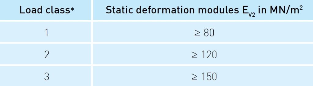
* See table 1. Load classification
Sub-base layer on an inverted roof construction
In the design of an inverted roof construction, moisture diffusion measures should be observed at all times. The installation of a vapour control layer on top of the thermal insulation is not permitted.
As compaction of non-hydraulically bonded “no-fines” sub-base material (i.e.: a material with no particles smaller than 1 mm) is difficult, the depth of the sub-base layer should be increased accordingly.
For each individual object it must be determined whether the moisture diffusion of the ND Drainage Systems Type “sv”, is compatible with the installation of a “no-fines” sub-base layer.
To check compaction is complete and correct, static or dynamic plate load tests should be undertaken. The most suitable type of vibrating plate compactor needs to be agreed with the design engineer.
Sub-base layer on a warm roof construction / roof construction without thermal insulation
The sub-base material should consist of crushed natural material with a granular size of 0/22 mm, 0/32 mm or 0/45 mm. In order to prevent damage to the roof outlets, only a limited amount of calcium hydrate may be leached from the sub-base material. This requirement can be relaxed in those cases where the collection and discharge of stormwater does not take place by roof outlets but is directed over the roof edge.
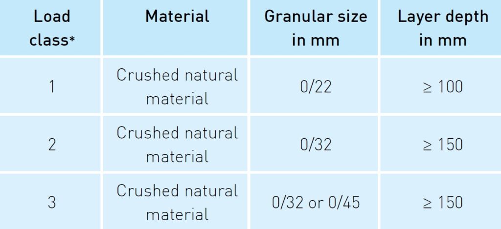
* See table 1. Load classification
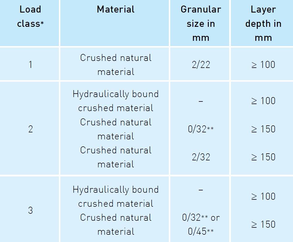
* See table 1. Load classification
** Suitability to be demonstrated by the manufacturer of the thermal
insulation
2.8 Levelling layer
In order to overcome height differences and / or to create falls, it may be necessary to install a levelling layer beneath pedestrian-only elemental pavements (load class 1).
The levelling layer is a combination of the laying course and the sub-base layer. The paving is laid directly onto the levelling layer.
Joint filling materials need to be carefully graded to suit both the actual joint width and the grading of the levelling layer material.
This layer can consist of natural crushed material with a granular
size of:
- 2/8 mm
- 3/9 mm.
The layer depth is a minimum of 50 mm and a maximum of 150 mm.
Once the paving layer has been placed and cut-in as necessary, the whole composition is compacted.
Where the levelling depth is greater than 150 mm, the levelling layer consists of crushed natural material with a granular size of 2/22 mm. The paving is laid on a separately installed laying course of crushed natural material with a granular size described above.
2.9 Laying course
The laying course is required to accommodate variation in thickness of the paving units and to even out irregularity in the sub-base layer, as well as providing stability to the paving units. The laying course should be as shallow as possible; however, when the loads are reduced the depth of the laying course can increase slightly, because the risk of deformation is reduced.
The bedding material used can consist of crushed natural material with a granular size of:
- 0/4 mm
- 0/5 mm
- 0/11 mm*
- 1/3 mm
- 2/5 mm.
On an inverted roof construction it might be necessary to use bedding material that is classed as moisture diffusion open or “no-fines” i.e. no particles smaller than 1 mm granular size.
Jointing materials need to be carefully graded to suit the grading of the bedding material.
Granular sizes of bedding materials that can be used for a moisture diffusion composition:
- 1/3 mm
- 2/5 mm
The depth of the laying course following compaction should be 30-50 mm. When paving blocks are installed with a thickness of ≥120 mm the laying course should be ≥ 40 mm with a granular size bedding material of 0/11 mm. Depending on the expected load and the type of paving to be used, the bedding material can be installed directly on top of the Drainage Systems.
*paving blocks thickness ≥ 120 mm – depth laying course ≥ 40 mm
To be continued.
2.10 Paving
Podium and/or parking roof decks combined with intensive green roofs
Podium deck and Parking Deck Systems
Podium Deck System – load class 1
Warm roof construction/roof construction
a. Build-up without sub-base layer
b. Build-up including sub-base layer
c. Build-up including levelling layer
d. Build-up including grass tiles
Inverted roof construction
a. Build-up without sub-base layer
b. Build-up including levelling layer
Park Deck System – cars – load class 2
Warm roof construction/roof construction
a. Build-up without sub-base layer
b. Build-up using larger concrete flags/slabs without sub-base layer
c. Build-up including sub-base layer
d. Build-up including grass tiles
Inverted roof construction
a. Build-up without sub-base layer
b. Build-up using larger concrete flags/slabs without sub-base layer
c. Build-up including sub-base layer
Park Deck System – heavy goods vehicles – load class 3
Warm roof construction/ roof construction
a. Build-up using large format concrete flags/slabs without sub-base layer
b. Build-up including sub-base layer
c. Build-up including grass tiles
Inverted roof construction
a. Build-up using larger concrete flags/slabs without sub-base layer
b. Build-up including sub-base layer
Appendix A – Index test: Assessment of the level of protection provided by the protection layer
Appendix B – Performance test: Assessment of the performance and behaviour of a pavement structure under simulated trafficking conditions performed at the Technical University Munich
Composition of an parking deck – load class 2 combined with intensive planting scheme